in Exchange server console under mail flow settings disable the required authentication for all senders.
Tuesday, February 14, 2012
failover cluster win2008
Introduction

Figure . Failover clustering

2. Active/Passive cluster model:


 7. Heartbeat.
The cluster’s health-monitoring mechanism between cluster nodes. This health checking allows nodes to detect failures of other servers in the failover cluster by sending packets to each other’s network interfaces. The heartbeat exchange enables each node to check the availability of other nodes and their applications. If a server fails to respond to a heartbeat exchange, the surviving servers initiate failover processes including ownership arbitration for resources and applications owned by the failed server.
The heartbeat is simply packets sent from the Passive node to the Active node. When the Passive node doesn’t see the Active node anymore, it comes up online


![clip_image001[6]](http://winadmins.files.wordpress.com/2011/10/clip_image0016_thumb.gif?w=244&h=218 "clip_image001[6]") 13. LUN
13. LUN

14. Services and Applications group
![clip_image001[4]](http://winadmins.files.wordpress.com/2011/10/clip_image0014_thumb.gif?w=1&h=1 "clip_image001[4]") Why quorum is necessary
Why quorum is necessary
For a 2-node multi-site cluster configuration, the Microsoft recommended configuration is a Node and File Share Majority quorum
Step –1 Configure the Cluster
Add the Failover Clustering feature to both nodes of your cluster. Follow the below steps:
 3. Follow the instructions in the wizard to complete the installation of the feature. When the wizard finishes, close it.
4. Repeat the process for each server that you want to include in the cluster.
5. Next you will want to have a look at your network connections. It is best if you rename the connections on each of your servers to reflect the network that they represent. This will make things easier to remember later.
Go to properties of Cluster (or private) network and check out register the connection’s addresses in DNS.

6. Next, go to Advanced Settings of your Network Connections (hit Alt to see Advanced Settings menu) of each server and make sure the Public network (LAN) is first in the list:

Step 2 – Validate the Cluster Configuration:
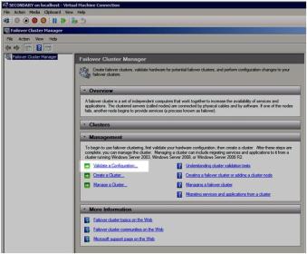
1. Open up the Failover Cluster Manager and click on Validate a Configuration.
2. The Validation Wizard launches and presents you the first screen as shown below. Add the two servers in your cluster and click Next to continue.

3. we need this cluster to be supported so we must run all the needed tests

4. Select run all tests.

5. Click next till it gives the report like below

When you click on view report, it will display the report similar as below:

Step 2 – Create a Cluster:
In the Failover Cluster Manager, click on Create a Cluster.

The next step is that you must create a name for this cluster and IP for administering this cluster. This will be the name that you will use to administer the cluster, not the name of the SQL cluster resource which you will create later. Enter a unique name and IP address and click Next.
Note: This is also the computer name that will need permission to the File Share Witness as described later in this document.

Confirm your choices and click Next.

Click Next till finish, it will create the cluster by name MYCLUSTER.
Step 3 – Implementing a Node and File Share Majority quorum
First, we need to identify the server that will hold our File Share witness. This File Share witness should be located in a 3rd location, accessible by both nodes of the cluster. Once you have identified the server, share a folder as you normally would share a folder. In my case, I create a share called MYCLUSTER on a server named NYDC01
.


 On the next screen choose Node and File Share Majority and click Next.


A failover cluster is a group of independent computers that work together to increase the availability of applications and services. The clustered servers (called nodes) are connected by physical cables and by software. If one of the cluster nodes fails, another node begins to provide service (a process known as failover). Users experience a minimum of disruptions in service.
Windows Server Failover Clustering (WSFC) is a feature that can help ensure that an organization’s critical applications and services, such as e-mail, databases, or line-of-business applications, are available whenever they are needed. Clustering can help build redundancy into an infrastructure and eliminate single points of failure. This, in turn, helps reduce downtime, guards against data loss, and increases the return on investment.
Failover clusters provide support for mission-critical applications—such as databases, messaging systems, file and print services, and virtualized workloads—that require high availability, scalability, and reliability.
What is a Cluster?
Cluster is a group of machines acting as a single entity to provide resources and services to the network. In time of failure, a failover will occur to a system in that group that will maintain availability of those resources to the network.How Failover Clusters Work?
A failover cluster is a group of independent computers, or nodes, that are physically connected by a local-area network (LAN) or a wide-area network (WAN) and that are programmatically connected by cluster software. The group of nodes is managed as a single system and shares a common namespace. The group usually includes multiple network connections and data storage connected to the nodes via storage area networks (SANs). The failover cluster operates by moving resources between nodes to provide service if system components fail.
Normally, if a server that is running a particular application crashes, the application will be unavailable until the server is fixed. Failover clustering addresses this situation by detecting hardware or software faults and immediately restarting the application on another node without requiring administrative intervention—a process known as failover. Users can continue to access the service and may be completely unaware that it is now being provided from a different server

Figure . Failover clustering
Failover Clustering Terminology
1. Failover and Failback Clustering Failover is the act of another server in the cluster group taking over where the failed server left off. An example of a failover system can be seen in below Figure. If you have a two-node cluster for file access and one fails, the service will failover to another server in the cluster. Failback is the capability of the failed server to come back online and take the load back from the node the original server failed over to.
2. Active/Passive cluster model:
Active/Passive is defined as a cluster group where one server is handling the entire load and, in case of failure and disaster, a Passive node is standing by waiting for failover.
· One node in the failover cluster typically sits idle until a failover occurs. After a failover, this passive node becomes active and provides services to clients. Because it was passive, it presumably has enough capacity to serve the failed-over application without performance degradation.

3. Active/Active failover cluster model
All nodes in the failover cluster are functioning and serving clients. If a node fails, the resource will move to another node and continue to function normally, assuming that the new server has enough capacity to handle the additional workload.
4. Resource. A hardware or software component in a failover cluster (such as a disk, an IP address, or a network name).
5. Resource group.
A combination of resources that are managed as a unit of failover. Resource groups are logical collections of cluster resources. Typically a resource group is made up of logically related resources such as applications and their associated peripherals and data. However, resource groups can contain cluster entities that are related only by administrative needs, such as an administrative collection of virtual server names and IP addresses. A resource group can be owned by only one node at a time and individual resources within a group must exist on the node that currently owns the group. At any given instance, different servers in the cluster cannot own different resources in the same resource group.
6. Dependency. An alliance between two or more resources in the cluster architecture.

The cluster’s health-monitoring mechanism between cluster nodes. This health checking allows nodes to detect failures of other servers in the failover cluster by sending packets to each other’s network interfaces. The heartbeat exchange enables each node to check the availability of other nodes and their applications. If a server fails to respond to a heartbeat exchange, the surviving servers initiate failover processes including ownership arbitration for resources and applications owned by the failed server.
The heartbeat is simply packets sent from the Passive node to the Active node. When the Passive node doesn’t see the Active node anymore, it comes up online

8. Membership. The orderly addition and removal of nodes to and from the cluster.
9. Global update. The propagation of cluster configuration changes to all cluster members.
10. Cluster registry. The cluster database, stored on each node and on the quorum resource, maintains configuration information (including resources and parameters) for each member of the cluster.
11. Virtual server. A combination of configuration information and cluster resources, such as an IP address, a network name, and application resources.
Applications and services running on a server cluster can be exposed to users and workstations as virtual servers. To users and clients, connecting to an application or service running as a clustered virtual server appears to be the same process as connecting to a single, physical server. In fact, the connection to a virtual server can be hosted by any node in the cluster. The user or client application will not know which node is actually hosting the virtual server.


12. Shared storage.
All nodes in the failover cluster must be able to access data on shared storage. The highly available workloads write their data to this shared storage. Therefore, if a node fails, when the resource is restarted on another node, the new node can read the same data from the shared storage that the previous node was accessing. Shared storage can be created with iSCSI, Serial Attached SCSI, or Fibre Channel, provided that it supports persistent reservations.
![clip_image001[6]](http://winadmins.files.wordpress.com/2011/10/clip_image0016.gif "clip_image001[6]")
LUN stands for Logical Unit Number. A LUN is used to identify a disk or a disk volume that is presented to a host server or multiple hosts by a shared storage array or a SAN. LUNs provided by shared storage arrays and SANs must meet many requirements before they can be used with failover clusters but when they do, all active nodes in the cluster must have exclusive access to these LUNs.
Storage volumes or logical unit numbers (LUNs) exposed to the nodes in a cluster must not be exposed to other servers, including servers in another cluster. The following diagram illustrates this.
14. Services and Applications group
Cluster resources are contained within a cluster in a logical set called a Services and Applications group or historically referred to as a cluster group. Services and Applications groups are the units of failover within the cluster. When a cluster resource fails and cannot be restarted automatically, the Services and Applications group this resource is a part of will be taken offline, moved to another node in the cluster, and the group will be brought back online.
15. Quorum
The cluster quorum maintains the definitive cluster configuration data and the current state of each node, each Services and Applications group, and each resource and network in the cluster. Furthermore, when each node reads the quorum data, depending on the information retrieved, the node determines if it should remain available, shut down the cluster, or activate any particular Services and Applications groups on the local node. To extend this even further, failover clusters can be configured to use one of four different cluster quorum models and essentially the quorum type chosen for a cluster defines the cluster. For example, a cluster that utilizes the Node and Disk Majority Quorum can be called a Node and Disk Majority cluster.
A quorum is simply a configuration database for Microsoft Cluster Service, and is stored in the quorum log file. A standard quorum uses a quorum log file that is located on a disk hosted on a shared storage interconnect that is accessible by all members of the cluster
When network problems occur, they can interfere with communication between cluster nodes. A small set of nodes might be able to communicate together across a functioning part of a network, but might not be able to communicate with a different set of nodes in another part of the network. This can cause serious issues. In this “split” situation, at least one of the sets of nodes must stop running as a cluster.
To prevent the issues that are caused by a split in the cluster, the cluster software requires that any set of nodes running as a cluster must use a voting algorithm to determine whether, at a given time, that set has quorum. Because a given cluster has a specific set of nodes and a specific quorum configuration, the cluster will know how many “votes” constitutes a majority (that is, a quorum). If the number drops below the majority, the cluster stops running. Nodes will still listen for the presence of other nodes, in case another node appears again on the network, but the nodes will not begin to function as a cluster until the quorum exists again.
For example, in a five node cluster that is using a node majority, consider what happens if nodes 1, 2, and 3 can communicate with each other but not with nodes 4 and 5. Nodes 1, 2, and 3 constitute a majority, and they continue running as a cluster. Nodes 4 and 5 are a minority and stop running as a cluster, which prevents the problems of a “split” situation. If node 3 loses communication with other nodes, all nodes stop running as a cluster. However, all functioning nodes will continue to listen for communication, so that when the network begins working again, the cluster can form and begin to run.
There are four quorum modes: - Node Majority: Each node that is available and in communication can vote. The cluster functions only with a majority of the votes, that is, more than half.
- Node and Disk Majority: Each node plus a designated disk in the cluster storage (the “disk witness”) can vote, whenever they are available and in communication. The cluster functions only with a majority of the votes, that is, more than half.
- Node and File Share Majority: Each node plus a designated file share created by the administrator (the “file share witness”) can vote, whenever they are available and in communication. The cluster functions only with a majority of the votes, that is, more than half.
- No Majority: Disk Only. The cluster has quorum if one node is available and in communication with a specific disk in the cluster storage. Only the nodes that are also in communication with that disk can join the cluster. This is equivalent to the quorum disk in Windows Server 2003. The disk is a single point of failure, so only select scenarios should implement this quorum mode.
- 16. Witness Disk – The witness disk is a disk in the cluster storage that is designated to hold a copy of the cluster configuration database. (A witness disk is part of some, not all, quorum configurations.)
Multi-site cluster is a disaster recovery solution and a high availability solution all rolled into one. A multi-site cluster gives you the highest recovery point objective (RTO) and recovery time objective (RTO) available for your critical applications. With the introduction of Windows Server 2008 failover clustering a multi-site cluster has become much more feasible with the introduction of cross subnet failover and support for high latency network communications.
Which editions include failover clustering?
The failover cluster feature is available in Windows Server 2008 R2 Enterprise and Windows Server 2008 R2 Datacenter. The feature is not available in Windows Web Server 2008 R2 or Windows Server 2008 R2 Standard
Network ConsiderationsAll Microsoft failover clusters must have redundant network communication paths. This ensures that a failure of any one communication path will not result in a false failover and ensures that your cluster remains highly available. A multi-site cluster has this requirement as well, so you will want to plan your network with that in mind. There are generally two things that will have to travel between nodes: replication traffic and cluster heartbeats. In addition to that, you will also need to consider client connectivity and cluster management activity
Quorum model:For a 2-node multi-site cluster configuration, the Microsoft recommended configuration is a Node and File Share Majority quorum
Step –1 Configure the Cluster
Add the Failover Clustering feature to both nodes of your cluster. Follow the below steps:
1. Click Start, click Administrative Tools, and then click Server Manager. (If the User Account Control dialog box appears, confirm that the action it displays is what you want, and then click Continue.)
2. In Server Manager, under Features Summary, click Add Features. Select Failover Clustering, and then click Install

4. Repeat the process for each server that you want to include in the cluster.
5. Next you will want to have a look at your network connections. It is best if you rename the connections on each of your servers to reflect the network that they represent. This will make things easier to remember later.
Go to properties of Cluster (or private) network and check out register the connection’s addresses in DNS.

6. Next, go to Advanced Settings of your Network Connections (hit Alt to see Advanced Settings menu) of each server and make sure the Public network (LAN) is first in the list:

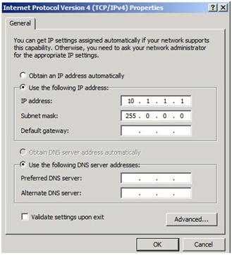
7. Your private network should only contain an IP address and Subnet mask. No Default Gateway or DNS servers should be defined. Your nodes need to be able to communicate across this network, so make sure the servers can communicate across this network; add static routes if necessary.
Step 2 – Validate the Cluster Configuration:
1. Open up the Failover Cluster Manager and click on Validate a Configuration.
2. The Validation Wizard launches and presents you the first screen as shown below. Add the two servers in your cluster and click Next to continue.

3. we need this cluster to be supported so we must run all the needed tests

4. Select run all tests.

5. Click next till it gives the report like below

When you click on view report, it will display the report similar as below:

Step 2 – Create a Cluster:
In the Failover Cluster Manager, click on Create a Cluster.

The next step is that you must create a name for this cluster and IP for administering this cluster. This will be the name that you will use to administer the cluster, not the name of the SQL cluster resource which you will create later. Enter a unique name and IP address and click Next.
Note: This is also the computer name that will need permission to the File Share Witness as described later in this document.

Confirm your choices and click Next.

Click Next till finish, it will create the cluster by name MYCLUSTER.
Step 3 – Implementing a Node and File Share Majority quorum
First, we need to identify the server that will hold our File Share witness. This File Share witness should be located in a 3rd location, accessible by both nodes of the cluster. Once you have identified the server, share a folder as you normally would share a folder. In my case, I create a share called MYCLUSTER on a server named NYDC01
.

The key thing to remember about this share is that you must give the cluster computer name read/write permissions to the share at both the Share level and NTFS level permissions. You will need to make sure you give the cluster computer account read/write permissions in both shared and NTFS for MYCLUSTER share.


Now with the shared folder in place and the appropriate permissions assigned, you are ready to change your quorum type. From Failover Cluster Manager, right-click on your cluster, choose More Actions and Configure Cluster Quorum Settings.


In this screen, enter the path to the file share you previously created and click Next.

Confirm that the information is correct and click Next till summary page and click Finish.
Now when you view your cluster, the Quorum Configuration should say “Node and File Share Majority” as shown below.

The steps I have outlined up until this point apply to any multi-site cluster, whether it is a SQL, Exchange, File Server or other type of failover cluster. The next step in creating a multi-site cluster involves integrating your storage and replication solution into the failover cluster
Subscribe to:
Posts (Atom)